In Door Localization with UWB
November 16, 2022 - Reading time: 7 minutes
Intro
I'm working an company which is manufactures own access-control systems. With my join to crew the company started to develop some kinda in door localization system with RF at UWB-band. The developed device, harness multiple wireless technologies. For ranging and the data network uses UWB. GPS is used for outdoor positioning and time management. For local readout of data end setting parameters added Bluetooth. Below the most important RF parameters and features of these technologies are written down.
UWB
Ultra-wideband (UWB, ultra wideband, ultra-wide band and ultraband) is a radio technology that can use a very low energy level for short-range, high-bandwidth communications over a large portion of the radio spectrum. Ultra-wideband has, as detailed in the IEEE 802.15.4 standard, a number of frequency channels of at least 500MHz wide around the 3-6GHz range. Signalling over a wide frequency range, as opposed to narrowband RF technologies such as WiFi and Bluetooth which signal at a certain frequency (2.4GHz), means using a narrow pulse in time-domain. UWB has traditional applications in non-cooperative radar imaging. Most recent applications target sensor data collection, precise locating, and tracking. UWB support started to appear in high-end smartphones.
Characteristics
Ultra-wideband is a technology for transmitting information across a wide bandwidth (>500 MHz). This allows for the transmission of a large amount of signal energy without interfering with conventional narrowband and carrier wave transmission in the same frequency band. Regulatory limits in many countries allow for this efficient use of radio bandwidth, and enable high-data-rate personal area network (PAN) wireless connectivity, longer-range low-data-rate applications, and the transparent co-existence of radar and imaging systems with existing communications systems.
Ultra-wideband was formerly known as pulse radio, but the FCC and the International Telecommunication Union Radiocommunication Sector (ITU-R) currently define UWB as an antenna transmission for which emitted signal bandwidth exceeds the lesser of 500 MHz or 20% of the arithmetic center frequency. Thus, pulse-based systems—where each transmitted pulse occupies the UWB bandwidth (or an aggregate of at least 500 MHz of a narrow-band carrier; for example, orthogonal frequency-division multiplexing (OFDM))—can access the UWB spectrum under the rules.
Theory
A significant difference between conventional radio transmissions and UWB is that conventional systems transmit information by varying the power level, frequency, and/or phase of a sinusoidal wave. UWB transmissions transmit information by generating radio energy at specific time intervals and occupying a large bandwidth, thus enabling pulse-position or time modulation. The information can also be modulated on UWB signals (pulses) by encoding the polarity of the pulse, its amplitude and/or by using orthogonal pulses. UWB pulses can be sent sporadically at relatively low pulse rates to support time or position modulation, but can also be sent at rates up to the inverse of the UWB pulse bandwidth. Pulse-UWB systems have been demonstrated at channel pulse rates in excess of 1.3 billion pulses per second using a continuous stream of UWB pulses (Continuous Pulse UWB or C-UWB), while supporting forward error-correction encoded data rates in excess of 675 Mbit/s.
A UWB radio system can be used to determine the "time of flight" of the transmission at various frequencies. This helps overcome multipath propagation, since some of the frequencies have a line-of-sight trajectory, while other indirect paths have longer delays. With a cooperative symmetric two-way metering technique, distances can be measured to high resolution and accuracy.
Technology Details
I'm working an company which is manufacturing own access-control systems. With my join to crew the company started to develop some kinda in door localization system with RF at UWB-band. The developed device, harness multiple wireless technologies. For ranging and the data network uses UWB. GPS is used for outdoor positioning and time management. For local readout of data end setting parameters added Bluetooth. Below the most important RF parameters and features of these technologies are written down.
Why UWB?
Because of it’s wide frequfency range (and inversely related, it’s narrow pulse width), UWB has unique characteristics and capabilities when compared to other technologies:
- UWB is not susceptible to narrowband interference,
- UWB can provide very accurate ranging,
- UWB can provide a secure communication channel.
Channels & Bandwidths
There are 6 channels to choose from with the following characteristics.
| Channel | Centre Frequency [MHz] | Bandwidth [MHz] |
|---|---|---|
| 1 | 3494.4 | 499.2 |
| 2 | 3993.6 | 499.2 |
| 3 | 4492.8 | 499.2 |
| 4 | 3993.6 | 1331.2 |
| 5 | 6489.6 | 499.2 |
| 7 | 6489.6 | 1081.6 |
You can freely choose between these channels in Engine. Note that it might take up to 2 minutes for the system to be fully switched to a different channel.
GNSS/GPS
Apart from positioning in regions where has no UWB coverage, GPS provides a useful timing signal.
Channels & Bandwidths
| Channel | Centre Frequency [MHz] | Bandwidth [MHz] |
|---|---|---|
| L1 | 1575.42 | 15.345 |
| L2 | 1227.6 | 11.0 |
| L3 | 1176.45 | 12.5 |
Bluetooth
The device allows configuration and read-out via BLE.f
Channels & Bandwidths
| Channel | Centre Frequency [MHz] |
|---|---|
| n = 0..78 | 2.402 + n |
Positioning algorithms
The position of an object can be determined in many different ways. It can be based on the Time Difference Of Arrival (TDOA) of the signals or by calculating the distance between the tags and the anchors via a method called Two Way Ranging (TWR). Also measuring the Received Signal Strength (RSS) gives you an idea of the distance between the sender and receiver. When the angle of the propagation of the signal is measured, Angle of Arrival (AOA) could be applied. For each of the methods, different implementations and variations exist. All algorithms have their pros and cons, which I will discuss below.
The most relevant algorithms for us are TWR and TDOA, that's why they will be discussed in more detail. TWR is more accurate than TDOA, but it is more CPU hungry and needs more signals in the air. By default, the engine runs on the PC and the tag itself is not aware of its position (TDOA1 and TWR1). For both schemes, there is however an alternative in which the positions are calculated on the tag itself (TDOA2 and TWR2).
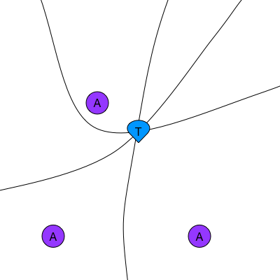
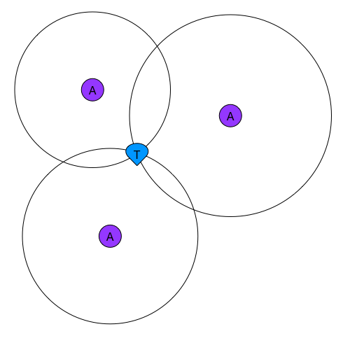
TDOA
Time Differences (TDs) yield hyperbolas. The position of the tag is calculated by calculating the intersection of the hyperbolas. Two anchors yield one TD (as opposed to only one anchor for one distance). This means a minimum of 3 anchors are necessary to calculate one 2D position and 4 anchors for a 3D position. The clocks of the nodes need to be synchronized. The better the synchronization, the higher the accuracy of the positions. Tags don't need to be active very often so this method is power consumption friendly. There is differentiate between 2 schemes (TDOA1 and TDOA2) based on where the time differences are measured.
TDOA1
The time differences are calculated on the anchors and offloaded to the system. The tags only need to 'blink' once for a position to be calculated, which means the tag power consumption is particularly low in this scheme.
TDOA2
The time differences are calculated on the tags, and thus the position can also be calculated on the tag. If this position doesn't need to be offloaded to the system, an infinite amount of tags can be used in this scheme. This scheme is similar to how GNSS/GPS works.
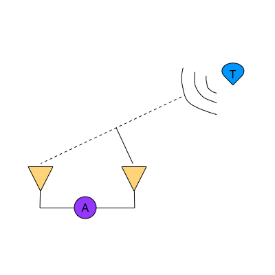
TWR
Two Way Ranging is a Time of Flight (TOF) method. The time of the propagation of the signal is measured between the transmitter and the receiver. A signal is sent from a tag to an anchor and back (hence the 'two way'). It needs to be sent back because the clocks of the anchors and tags are not synchronized. This means that the timestamps taken at the tag are on a different timebase than those taken on the anchor. With the 4 timestamps (2x transmission and 2x reception) you can accurately calculate how long the signal has traveled back and forth between the nodes. Dividing that time by 2 yields the TOF and thus the distance. The airtime of the nodes is higher then in TDOA, so less positions can be calculated.
TWR1
The distances are calculated on the anchors and offloaded to the system. The position is calculated on a PC.
TWR2
The distances are calculated on the tags, where the position is also calculated.
AOA
Angle of Arrival is a method in which the direction of the propagation of the RF-signal is calculated on the receiving node, for example based on the phase difference measured on 2 different antennas. A 2D position can be derived from 2 angles with some simple triangulation.
Comparison
| PARAMETER/ALGORITHM | TWR1 | TWR2 | TDOA1 | TDOA2 | AOA | RSSI |
|---|---|---|---|---|---|---|
| Power consumption | - | 0 | 0 | + | - | - |
| Position Accuracy | ++ | 0 | 0 | + | - | - |
| Position Stability | ++ | 0 | 0 | + | - | - |
| CPU load | + | 0 | 0 | + | - | - |
| Bandwith usage | - | 0 | 0 | + | - | - |
| Minimum amount of nodes | + | + | 0 | + | - | - |
| Tag Density | - | 0 | 0 | + | - | - |
| Scalability | + | + | 0 | + | - | - |
Conclusion
Depending on your use-case, any algorithm could be the best for you. Are you mostly looking for accuracy? Then go for TWR. Is energy consumption the most relevant? Choose TDOA. Angle of Arrival can be useful if you don't want to have a lot of hardware and accuracy is not that important.